Inventor-Designer: Carlo Macrì
Inventor-Designer: Carlo Macrì
Inventor-Designer: Carlo Macrì'
THE PROJECT
The basis idea which pushed me to planning this new type of military vessel is that concerning the
possibility to have at own disposal in a quick time, almost everywhere in th world, a great and functional
aeronaval base suitable also for the take off and the landing of the biggest and powerful airfreighters.In case of grave political crisis in geographic areas particularely important under the strategical, econo-
mical and social aspect, as well as for the balance and the safety of the international relations, this
structure could enable its owners to carry out rapid, efficacious and heavy weight interventions without
before having to resolve too much logistical problems and waiting the long times needed for the activa-
tion of adequate ports and airports on the territory of friendly Countries.The opportunity to may utilize, after having reached the pre-established area, as a unique landing strip
a series of ships with different functions like those who usually are fulfilled by the vessels which escort
the aircraft carriers driving a “Task Force”, could be the fundamental element of a likely future winning
strategy for indispensable and urgent military interventions of big importance and at wide radius, thanks
to its valuable qualities of high quickness in the beforehand arranging of offensive apparatus and of its
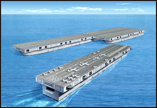
great operating incisiveness.Such aeronaval base, rapidly transferable and easily and swifty composable could be formed, as already
mentioned, apart one or more “full-deck” aircraft carriers having conventional functions, by a certain number
of auxiliary or support ships of the following kind, them also “full-deck”:a) - assault-ship for the conveyance of landing troops, anphibian means, and armoured means;
b) - helicopters carrier, supplied with various kind of this craft used for reconnaissance, antisubmarine
and fighting activities and fit for transport of special storm-troops with their particular means utilizable for
the most different operative needs, it should be endowed also with some little submarines right for blitz
and other robot-type usable for checking, maintenance and, if necessary for little repairs to the hulls;c) - various supply ships, for munitions, provisions, fuels and mineral water reserve, also arranged in
advance for the carrying of the particular metallic, semisubmerged antitorpedo barriers and their pertinent
"motorized buoys" for its transfer and linking, afterwards better described, which are usable for the base
distant protection when it is statically positioned like a unique “Grand Convoy” after the joining of the
numerous ships that constitute it;d) - repair ship, endowed also with demountable covered hangars and with appropriate cranes and
elevators, it is also furnished with a suitable spare storehouse for the most probable and varied necessities;e) - hospital ship, well equipped and fit to face also the hardest and numerous medical exigence wich
should happen.Naturally, besides the above mentioned naval units, a “task force” of this type should be accompanied with
a sufficient number of conventional escort ships like i.e.: cruisers, destroyers or missile launching frigates,
nuclear submarines, different kind of mine-sweeper, deep sea tugs and at least one dockyard vessel of
adequate dimensions to permit the on the spot repairing of the little and middle tonnage ships.For a better defense of the aeronaval base formed by adopting one of the different possible scheme of
joining the various hulls, it should be opportune to dispose perimetrically, at a distance of about 1.000
metres, a strong and efficacious metallic semisubmerged antitorpedo barrier, useful also to impede
ramming attacks and intrusions by surface means.This special barrier, carried in the pre-established zone by the great “full-deck” tenders above mentioned
or byother big freighters, should be constituted by a series of wide diameter steel pipes closed at their
extremities and having the function of floating body to which they are firmly hooked square “panels” having
sides of about 20 metres and formed with a strong frame which hold a tough wire netting with square stitch
12 centimetres wide.Such “panels” vertically bathed in the sea and keeped up by the above-said floating pipes segments are,
of course, linkable each other by special eyelet and jointed hooks, better pointed out in the relative drawings,
they are positioned at the foreseen distance from the “Grand Convoy” by means of the particular self-achoring
motorized buoy and there maintained.Each of these special buoy, endowed with a light armament, at the middle of the broadsides pertinent
to the underlying hulls, are provided with couplers similar to those previously described and should carry you
either the function of outer look-out or that of joining element for a series of 10/12 floating barrier segments or
that of mobile component fit to open in some position, when required, a passage for all the boats or vessels
which for the most diversified reasons may be enabled to reach the central sheltered display.In proximity of a couple of the above-described buoies, inside the protected area, at a distance sufficient
to allow the ships passage, they should be positioned further barrier segments and motorized buoys in
order to avoid the making of unsheltered spaces during the opening and the shutting of the passages.
DESCRIPTION OF SOME EXTERNAL ELEMENTS COMMON TO ALL
“FULL-DECK” VESSELSOnly approximately, the comprehensive dimensions of each of these ships should be the following:
- overall length 350 metres - width of the hull 35 metres - overall deck width 70 metres - total height
from the keel to the fly deck 40 metres.1) - The whole superior section of the ship on which top lies the fly deck is mainly used for a stedy and
speedy junction of different naval units. The total height assumed for this is almost 12/13 metres and
make it possible the installation, at regular intervals, of a lot of retractile and raisable platforms that can
be moved by means of a sliding on particular tracks and can serve for varied uses as i.e.:
a) - radar and broadcasting antenna post
b) - missile launching ramp and pertinent parabolic antenna for remote control emplacement
c) - guns and anti-aircraft machine-guns emplacement
d) - sighting, flash-signalling and observations emplacement.Vertically, along the boundary of this superior section, at regular intervals, interpolate with the above-said
emplacements and with the stem and stern Command Bridges, they are placed the structures which permit
the junction of different vessels not only in order to create a unique and long landing strip but also where preset
wide and adequate squares for the staying, the maintenance and the repairing of the biggest bombers and air-cargo.These structures are essentially constituted by three elements:
a) - horizontal and vertical borders coated with a rubber thickness to reduce the impact between the external frames
of the various joining sectors;
b) - orifices for steel pipe segments having an hexagonal section placed nearby the four angles of the above said
sectors, they also furnished on its extremities with a rubber thickness, which serve for the initial block and the exact
junction of two ships joining sectors;
c) - central frames of joining sectors with a rectangular shape but having rounded-off angles, them also
rubber thickness coated, along whose perimeter it is prearranged a series of threaded orifices for the
insertion of appropriate screw bolt, which give, together with the above mentioned hexagonal size steel
pipes, steadiness and sturdiness to the whole “Great Convoy”.2) - In the hull’s broadside higher zone, under the superior section, they are positioned some fixed jutting
emplacements utilizable, as usually, for: loading and descharging of provisions and armaments; lowering
of service shallops and, in case of life-boat; throwing of torpedoes and depth bombs; small bridge for the
hooking of ladders for people’s on board access.3) - The large terrace at the stern may serve, besides as usual, for the aircraft's engines test and overhauling,
for an easier and faster loading of some kind of furnishements so that it can be avoided its long and difficult transfer
in the interior corridors and like directional place during the joining operations
of two ships.4) - The supplementary bow Command Bridge underlying the upper section has it also the directional function during
the joining operations and that of optical checking of the stretch of water created between two naval units already joined.5) - The great stern hatch may be used, as a rule, for: a) launching and recovering of anphibious means or for particular
boats utilizable for special operations at short and medium radius; b) launching and recovering of the distinctive covered
command sloops used for the shifting of Commander Officers and
for the on board Authorities’ visits.6) - According to the various types of ship, that is “true” aircraft carriers or auxiliary and support vessels,
whereas the upper section acting as landing strip shall be planned about with the same scheme, the hull’s broadside,
on the contrary, shall be planned in diversified shapes with the purpose to better perform the varied functions for which
they have been conceived.7) - this type of floating airport, for being easily found by aircraft coming back from different missions, in
case of location on more than 300 metres deep waters, should utilize the Geostationary Positioning System (G.P.S.).
The same, however, could be continuously utilizable, also in conditions of rough sea, thanks to a new stabilizing
system constituted by a lot of hydrodynamic resistance keel's panels, retractable and bathable till to a 35-40 metres
profundity. For what concerns the deck-landing it could
be effected also in conditions of variable but not very strong wind because it should be much facilitate
by the availability of a 70 metres wide strip, completely clear from every kind of obstacles!Other information pertinent further specific element of this innovating naval construction, already planned
either inside or outside, shall be furnished to those who are truly interested in its realization.
A military apparatus formed by a series of this type of aircraft carriers should be constituted with at least
6 (six) ships for having at own disposal a 1,400 metres long landing strip and adequate squares for the
resting, munitioning and maintenance of the biggest aircrafts; whereas if they would make ready a true
floating artificial island endowed with a sheltered harbour area, double landing strip each long 1,400
metres and more adequate squares, it should be needed the availability of 12 “full-deck” vessels.If we consider that each of theese "modular carrier" should cost about the same than one of the last
"Nimitz" class, at the moment under construction, the supposable comprehensive costs for a this kind
structure should be of about 30 Billion of US$ in the case of the single strip and of about 55 Billion of
US$ in the case of the island with harbour sheltered area and double landing strip.
Surely, they are very elevated costs but however much lower than those foreseen for the “Spatial Shield”.Moreover, the realization of such kind of carrier could be considered a positive and more realistic answer
to planners and supporters of the already abandoned project of Mobile Offshore Base (M.O.B.).At last, it must be considered that these new naval units could carry out the same functions of the
current single aircraft carriers and, little by little, in the future, they can replace them completely, offering
at the same time their own peculiar prerogative to may be joined rapidly each other for being utilized as
a great mobile airport.==================================
LAST UPDATINGS AND DEEPENINGS
If we consider the currently needed time currently needed for the realization of a new carrier model, after
having fulfilled the necessary effectiveness and feasibility verifications, that is from the first expense for
the preliminary project to the final disbursement of the estimated amount for first exemplar completion
and then to the new carrie launching, which are expected in at least 10-12 years, it should be useful for
interested persons and Institutions to begin right now to operate for setting up the planning of the
principal and more innovating basic elements.Particularly, thinking to United States that, at the moment, could be the only who could have a real
interest in carrying out such a project, althought themselves have some economic problems given from
recent elevated budget deficit; with reference to their foreseen turnover in the carrier sector, the first
original full-size exemplar of this new type of carrier could obtain initial funds starting from 2008 f.y.
for growing operative all around the 2020, that is about 3-4 years after the delivery of the current last
programmed model: the CVX 79 (CVX - 2).Of course, all the already foreseen improvement for this carrier, and those made in the preceding vessels,
the CVN 77 and CVN 78 (CVX - 1), that is "Commercial Ship Technologies/Solid State Control" -
"Integrated New Island" - "Electrical Generation and Distribution" - "New Propulsion Plant" - "Improved
Flight Deck" and "Improved Hull" should be transferred also to this "Modular Carrier" proposal.
AIRCRAFTS' DECK-LANDING AND TAKE-OFF PROBLEMS
This future carrier's generation in addition to being provided with at least a pair of the current steam-cata-
pults, should be equipped with new and, it seems, more functional electromagnetic catapults (EMALS)
which are in advanced realization state.In case this new launching system, also thanks to adequated insulation and shielding, should prove
to be really effective and without contraindications for the good functioning of the various ship's electronic
apparatus, because of the strong magnetic field created in the catapult's vicinity during its working, here
we should think to utilize it also for bigger size aircrafts launching.Even supposing to have at our disposal a 200 metres electromagnetic catapult, that is twice the lenght
compared to that at the moment under consideration, it alone, most probably, shouldn't be sufficient
for taking-off the more heavy aircrafts, tharefore we thought it should be, in any case, necessary to have
a much more long strip to allow the aeroplane could reach enough speed for take flight.Undoubtedly, if besides the 200 metres catapult, we should have at our disposal another 1,000 metres
long strip, here the probability to begin the flying, thanks to the higher acceleration given from aircraft's
engines during the additional trip, could become much more elevated.Moreover, if in addition to this longer strip we could have at our disposal a new generation of large aero-
planes equipped with one supplementary thruster, also to be utilized only for a brief time during the
taking-off course, there we could have the certainty to take flight using a much more short strip than
those now indispensable.--------------------------------------------------------
Whereas for what concerns the possibility of a safe deck-landing on this kind of strip formed by 4 (four)
joined carriers, we thought the utilization of 2 (two) other instruments additionally to that constituted by
the traditional arresting-gear formed by elastic ropes stretched few centimetres high the landing strip
at which is coupled the aircraft's pendent ventral hook.Excluding for different reasons the use of "tail parachute", the utilizable elements to shorten the needed
arresting way during the big aircrafts' deck-landing should be the following:1) - two or more "back-thrusters" that, with an appropriate and adjustable power may produce a contrary
thrust to aircraft's advancement march immediately its leaning on the deck strip;2) - constructing a new generation of large aircrafts fitted with a series of "F.O.B. Flaps" (Fuselage
Opening Braking Flaps) that could perform a remarkable aerodinamic resistance to aeroplane's advance-
ment, which so could stop on the limited disposable strip.These new aircraft's models either for conveyance or for bombing, thanks to the above indicated characte-
ristics, could be easily used either with the "joined carriers" (Floating Airport) or on the mainland where
they could be utilized landing strip much more short than currently.We can believe that such a type of aircraft could be very interesting not only for "Navy" but also for
"Marine Corps" and for "Air Force" who should participate in its realization taking upon themselves a share
of the necessary expenses for its planning and prototypes construction.
OTHER INTERESTING ANALYSIS AND REASONINGS
MAY BE REVIEWED AT THE END OF ITALIAN VERSION
Details of the principal structures
emerging from the sea level
E-mail address: artificial@inwind.it
Internet address: http://carlomacriprojects.it
Telephone: + 39 051 821609
PATENTED - All rights reserved
Back to Top